This page describes some experiments we did to know if we can use the PPS from an Intel Ethernet Controller on the ORS.
Prerequisites
Hardware
You need 3 machines:
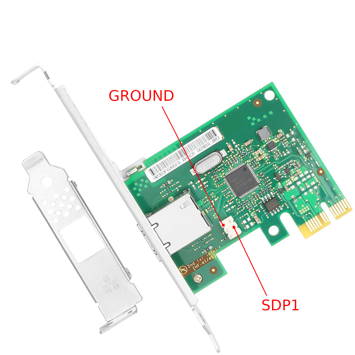
- machine1 with a network card with I210 like this one (it is important to be able to access the SDP1 pin of the I210 controller)
- machine1 with a network card with I210 like this one (it is important to be able to access the SDP1 pin of the I210 controller)
- machine3 with any network card (if this card support hardware ptp you will have better result)
You should plug an oscilloscope to SDP1 pin of both cards.
Connect all 3 machines to a switch.
Software
You should install a Linux distribution (somehow recent) on the 3 machines (on my experiment, I used Fedora 34 and Ubuntu 22.04).
Then install "linuxptp" package on the 3 machines.
For the 2 machines with the I210 network card, you should also install testptp. In order to do this, download the source code from https://github.com/torvalds/linux/blob/master/tools/testing/selftests/ptp/testptp.c. Please be sure to use a version corresponding to your kernel (you can do "uname -a" on your machine to know the date of your kernel and then have a look at the history of the file). On my experiment, I used https://raw.githubusercontent.com/torvalds/linux/f64ae40de5efaa33c36f4e2226b33824ba1b42a7/tools/testing/selftests/ptp/testptp.c. Then, you should simply compile testptp with "gcc -o testptp testptp.c".
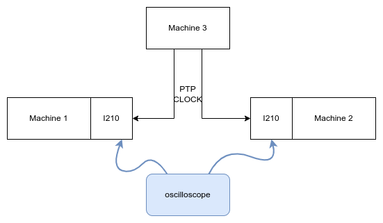
Experiment 1: sync both I210 PPS from another clock
For this first experiment, we simply try to synchronize both I210 network card clock from the 3rd machine and we measure the offset between the rising edge of both PPS signals.
Setup
On both machine1 and machine2, run the following commands:
# replace enp0s31f6 with the correct interface name
$ ptp_dev=`ethtool -T enp0s31f6 | awk '/PTP Hardware Clock:/ {print $4}'`
$ ./testptp -d /dev/ptp$ptp_dev -L 1,2
set pin function okay
$ ./testptp -d /dev/ptp$ptp_dev -l
name SDP0 index 0 func 0 chan 0
name SDP1 index 1 func 2 chan 0
name SDP2 index 2 func 0 chan 0
name SDP3 index 3 func 0 chan 0
$ ./testptp -d /dev/ptp$ptp_dev -p 1000000000
periodic output request okay
This will output the PPS on SDP1 and you should see the PPS on the oscilloscope. For now the 2 PPS signals are not synchronized.
Then you should run this command on machine3:
# replace enp0s31f6 with the correct interface name
# remove '-H' if your network card doesn't support hardware PTP
$ ptp4l -i enp0s31f6 -H -m
And you should run this command on both machine1 and machine2:
# replace enp0s31f6 with the correct interface name
$ ptp4l -i enp0s31f6 -s -H -m
Result
Then you should see on the oscilloscope that both rising edge of PPS signal happens at the same time. You should zoom in on the oscilloscope to see the difference between the 2 rising edge like this:
We can see here that the difference between the 2 edges is below +-50ns (square width is 50ns and the trigger is on the blue channel rising edge).
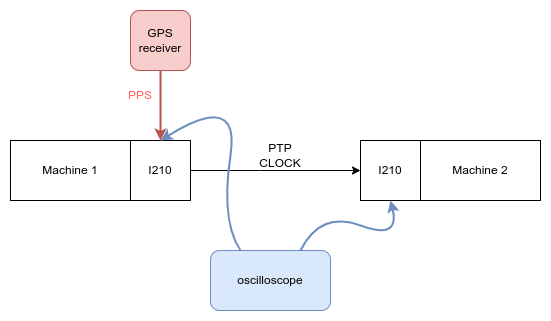
Experiment 2: Send PPS from GPS from one I210 to the other I210
For this experiment, we connect the PPS from a GPS receiver to the SDP1 pin of one I210 controller. This I210 will then transmit the clock through PTP to the other I210 controller.
Setup
On machine1, run the following commands:
# replace enp0s31f6 with the correct interface name
$ ts2phc -c enp0s31f6 -m -s generic --ts2phc.extts_correction 1 --ts2phc.extts_polarity "both" --ts2phc.pin_index 1 --ts2phc.pulsewidth 100000000 -l 6 &
$ ptp4l -i enp0s31f6 -H -m
On machine2, run the following commands:
# replace enp0s31f6 with the correct interface name
$ ptp_dev=`ethtool -T enp0s31f6 | awk '/PTP Hardware Clock:/ {print $4}'`
$ ./testptp -d /dev/ptp$ptp_dev -L 1,2
set pin function okay
$ ./testptp -d /dev/ptp$ptp_dev -l
name SDP0 index 0 func 0 chan 0
name SDP1 index 1 func 2 chan 0
name SDP2 index 2 func 0 chan 0
name SDP3 index 3 func 0 chan 0
$ ./testptp -d /dev/ptp$ptp_dev -p 1000000000
periodic output request okay
$ ptp4l -i enp0s31f6 -s -H -m
Result
Then you should see on the oscilloscope that the rising edge of PPS from GPS signal happens at the same time as falling edge of PPS output by machine2. You should zoom in on the oscilloscope to see the difference between the 2 edges like this:
We can see here that the difference between the 2 edges is below 50ns (a square width is 100ns and the trigger is on the blue channel rising edge).